


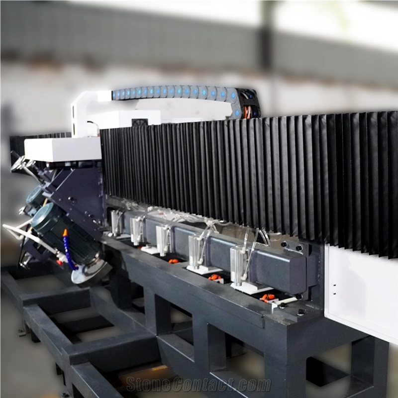
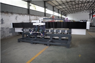
Triple-Head 45° Mitre Cutting Machine
FOB Price:$8100-8200


Supplier

Eatablished :Dec 26,2014
Main Product:
5 Axis CNC Bridge Saw, 4+1 CNC Bridge Saw , 45° Miter Cutter, Stone CNC Engraving Machine, Cutting And Edging Work Center, Trepanning Machine|

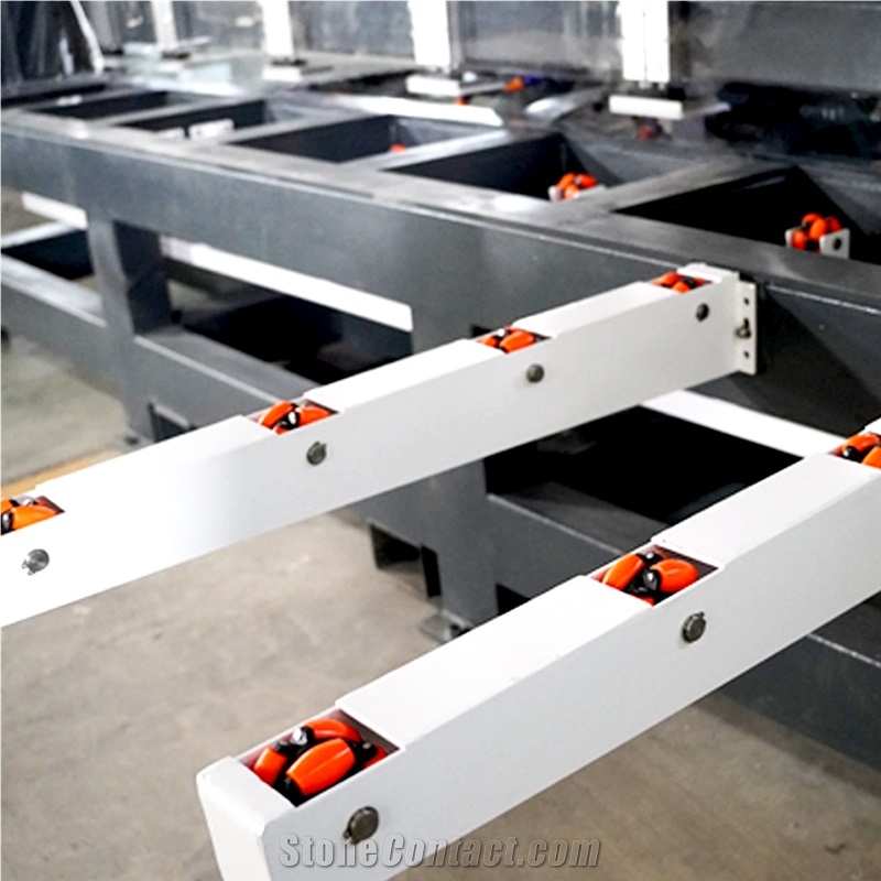
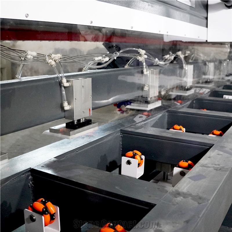
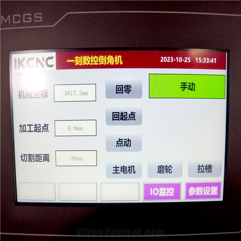
The whole frame adopts imported five-sided milling machine for precision milling, drilling. it is high precision, small deformation, head movement when processing, cylinder press plate fixed material, effectively avoid the size of the head. Pneumatic universal wheel lifting platform design, easy access to the plate, save labor, accurate positioning while solving the problem of water suction plate. The first head cutting, the second head grinding wheel and edge trimming, the third head milling groove, using the first cutting and the second grinding processing, mode, no edge and angle damaged. The 3heads can be used at the same time, and also can use only one head or two heads, easy to switch. CNC PLC automatic control, touch screen, can freely set the cutting speed, length automatic reserve, can be tangent and reversed. The structure is bridge rail hanging, better waterproof effect, avoid water corrosion, automatic oil injection system, more convenient maintenance.
Parameters |
Unit |
45 degree charmfer machine |
Spindle motor power |
kw |
7.5 |
Total power |
kw |
15 |
Number of spindle |
nr |
3 |
Machine overall width |
mm |
2200 |
Approx. Weight |
T |
1.8 |
Machine overall height |
mm |
1700 |
Max. working length |
mm |
3200 |
Machine overall length |
mm |
5700 |
Max. working thickness |
mm |
20 |
Water Consumption |
m3/h |
3 |
The working principle of a PLC (Programmable Logic Controller) system is based on cyclic scanning. The specific working process is as follows2:
Power - on Initialization Stage
When the PLC is powered on or switched from the stop mode to the run mode, it first performs internal initialization.
Loads the user program from non - volatile memory (such as EEPROM) into RAM.
Clears the status of all output modules (usually set to a safe state).
Checks the hardware status and communication to get ready for cyclic scanning.
Input Sampling Stage
The CPU of the PLC reads the current physical states of all input modules (both digital and analog) in sequence. For example, it reads whether a button is pressed (high level = 1), whether a sensor detects an object (high level = 1), or the current voltage/value of a potentiometer/temperature sensor (converted into a digital quantity).
The CPU stores all the input status values read at this moment in a specific area of the memory, called the "input image register" in a batch manner. After the input sampling is completed, even if the actual physical state of the input point changes, the state and data of the corresponding unit in the input image area will not be updated in this scanning cycle.
User Program Execution Stage
The CPU starts to scan and execute the user program stored in the memory in sequence, from top to bottom and from left to right.
When scanning each ladder diagram, it first scans the control circuit composed of various contacts on the left side of the ladder diagram, and performs logical operations on the control circuit composed of contacts in the order of left - first, right - second, top - first, and bottom - second. Then, according to the result of the logical operation, it refreshes the state of the corresponding bit of the logical coil in the system RAM storage area, or refreshes the state of the corresponding bit of the output coil in the I/O image area, or determines whether to execute the special function instructions specified in the ladder diagram.
During the execution of the user program, only the state and data of the input points in the I/O image area will not change, while the states and data of other output points and soft - devices in the I/O image area or the system RAM storage area may change. Moreover, the program execution result of the upper - ranked ladder diagram will affect the lower - ranked ladder diagrams that use these coils or data. Conversely, the state or data of the refreshed logical coil of the lower - ranked ladder diagram can only affect the upper - ranked program in the next scanning cycle.
Output Refresh Stage
After the scanning of the user program is completed, the CPU transfers all the current final calculation results (0 or 1) in the output image register to the output module in a batch manner.
The output module drives the physical load according to the received signal. For digital output, it turns on/off the relay contacts or lights up the LED. For analog output, it outputs the corresponding current (4 - 20mA) or voltage (0 - 10V) signal to drive regulating valves, frequency converters, etc. At this time, the state of the physical output point really changes.
Peripheral Communication and Service Processing Stage
The CPU performs communication processing, including communicating with programming devices (such as computers) to respond to programming/debugging requests, communicating with HMI (Human - Machine Interface), SCADA systems or other PLCs/devices to exchange data, and updating the status of remote I/O modules (in a distributed I/O system).
The CPU executes internal diagnosis, such as memory check, watchdog timer check (to prevent the program from getting into an infinite loop).
It also processes interrupt requests (if the interrupt program is configured).
Cyclic Operation
After a complete scanning cycle (input sampling → program execution → output refresh) is completed, the CPU immediately returns to the input sampling stage to start the next scanning cycle, and reads the new input status at this time.
The length of the scanning cycle depends on factors such as program length, complexity, instruction type, CPU speed, and the number of I/O points, usually ranging from a few milliseconds to tens of milliseconds. The cyclic scanning working mode endows the PLC with the characteristics of sequentiality, real - time performance, certainty, and anti - interference, which ensures the reliability and stability of industrial control.
The whole frame adopts imported five-sided miling machine for precision milling, drilling. it is high precisionsmall deformation, head movement when processing, cylinder press plate fixed material, effectively avoid the size
of the head.
Pneumatic universal wheel lifting platform design, easy access to the plate, save labor, accurate positioningwhile solving the problem of water suction plate.
The first head cutting, the second head grinding wheel and edge trimming, the third head milling groove, usingthe first cutting and the second grinding processing mode, no edge and angle damaged. The 3heads can be usedat the same time, and also can use only one head or two heads, easy to switch.
CNC PLC automatic control, touch screen, can freely set the cutting, speed, length automatic reserve, can betangent and reversed.
The structure is bridge rail hanging, better waterproof effect, avoid water corrosion, automatic oil injectionsystem, more convenient maintenance.
-

slab
-
-
-

Machine head
-
-

Electrical cabinet
-
-

Oil injector
-

blade
 Malaysia
2023
Malaysia
2023
4.8 / 5 Very satisfied
Far*** 
9/9/2025 9:48:26 PM
Mon*** 
8/21/2025 7:26:46 PM
Mar*** 
8/7/2025 8:42:22 PM
Ahm*** 
8/7/2025 9:20:59 AM
Related Products:

JINAN IKCNC TECHNOLOGY CO.,LTD

 China
China
 1YR
1YR

Tel:86-15615410983
Contact supplier
